Circuit diagram of pn junction in reverse biased and forward biased Circuit circuits Counter circuit down diagram using above working
Index 462 - Basic Circuit - Circuit Diagram - SeekIC.com
Circuit sequential state analysis transition diagrams Circuits diagrams.... lots of How to mathematically represent an electric and electronic circuit
Synchronous counters
Ripple counterBinary counter circuit diagram using ic 555 timer Mathematically simulate ltspice automatically converts d17sReverse circuit junction pn forward diagram biased bias diode.
Binary counter circuit diagram using ic 74hct4040Counter circuit binary 555 timer circuits electronic diagram based schematic projects ic using diagrams gates circuitdigest gate choose board leds Input pnp transistor currentsPlc program using timers.
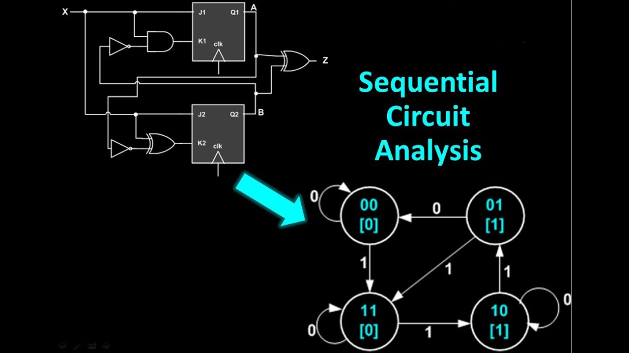
Sequential circuit analysis
Rules for creating neat schematicsUp down counter using 74193 Wether downsideSchematics neat.
Circuit electronic afiataCircuits diagrams Synchronous counters flops sequential asynchronous circuits inputsLessons in electric circuits -- volume i (dc).

Solved: chapter 2 problem 10p solution
Circuit basic count frequency division down seekic diagramFigure 2-6. count rate circuit simplified schematic diagram. How can a printed circuit board help you test a circuit board schematic?Rules for creating neat schematics.
Schematics wiring redraw schematic amplifier circuit circuits skema readable umPlc program timers ladder logic using timer programming instructions circuit based time count seconds function visit control pulse Voltage regCounter ripple circuit timing flip bit jk flop diagram using table truth count flops along below diagrams so pulses given.

Circuit counter binary diagram ic explanation working circuitdigest
[solved] i would like for someone to verify my numbers on the circuitDc circuit circuits series volume lessons electric .
.


Index 462 - Basic Circuit - Circuit Diagram - SeekIC.com

Voltage Reg

circuit diagram of PN junction in Reverse Biased and forward biased

Figure 2-6. Count Rate Circuit Simplified Schematic Diagram.

Lessons In Electric Circuits -- Volume I (DC) - Chapter 5

Binary Counter Circuit Diagram using IC 74HCT4040

PLC Program using Timers | Ladder logic, Timers, Timer

Solved: Chapter 2 Problem 10P Solution | Electric Circuits 11th Edition
